HID Ballast Wiring Diagrams for HID ballast kits including Metal Halide and High Pressure Sodium Lighting ballasts. Most magnetic HID ballasts are multi-tap, meaning they can be connected to several different voltages.
Step 1 – Preparations
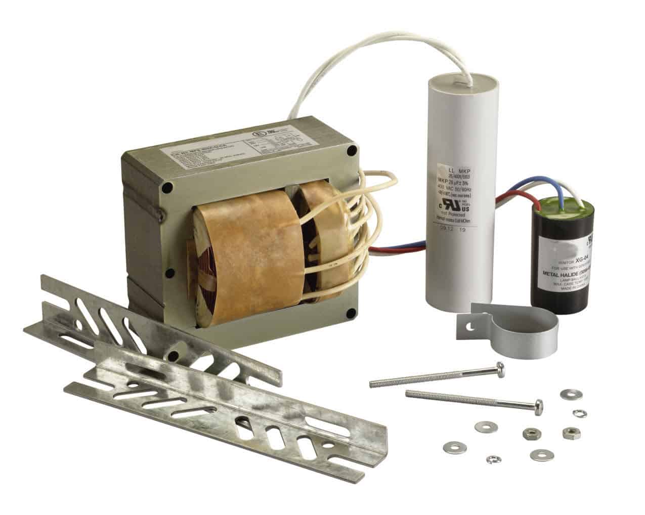
There are three basic parts inside the ballast: the transformer, the capacitor and the ignitor. Each of these parts can be bought separately. When purchasing individually, make sure to buy the correct rating for the home, usually 120V in most homes. In addition to these three, the HID ballast should also be wired to a bulb and socket; therefore, there is a need for a 14 gauge wire, wire nuts, power cord and male plug set. Also, obtain a wiring diagram for the ballast. This usually comes in the manual or written on the ballast enclosure.
Step 2 – Wiring the Internal Parts
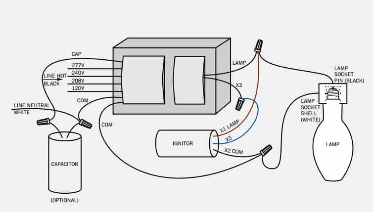
The wiring diagram shows three components connected to the lamp (the transformer, the capacitor and the ignitor). Inspect the two sides on the transformer to see its long side and the short side. Notice that wires come out of the device through two protuberances.
The capacitor has two wires and the ignitor has three wires (X1, X2 and X3). Keep in mind that the description on the wires is important when connecting them.
Locate the wire on the transformer with the word cap. Connect this wire to the capacitor and secure the connection with a wire nut. On the long side of the transformer, locate the wire marked X3 or 3. Connect this wire to the ignitor wire marked X3 or 3 as well. Be certain no bare wire is exposed.
Step 3 – Connecting the Ballast to the Socket and Lamp
To connect the ballast to the socket, get the white wire from the socket, locate the com2 or comX2 on both the short side of the transformer and the igniter and connect the 3 all together using a wire nut.
How to install a HID ballast? Locate the wire labeled lamp on the long side of the transformer and the X1 wire on the ignitor. Connect both of these together with the black wire coming from the socket. Connect all three using a wire nut.
Step 4 – Final Connections
There should be two wires coming out of the HID ballast’s short side labeled com and 120. Remove the sheathing from the power cord, and strip the insulation on both black and white wires about ½-inch. Connect the com wire to the white wire on the power cord and the 120 wire to the black wire. Make sure all connections are secured using wire nuts. Afterwards, connect the bare wire to the base of the transformer or to the enclosure. Install the enclosure to cover the magnetic ballast and tighten the screws.
Step 5 – How to install a HID ballast Testing
Check to make sure that all connections are correct and complete. Install a bulb onto the socket and plug the ballast to a power supply. If the light works, the wiring is successful.
Ballast Characteristics
Typical characteristics of ballasts used in HID lighting
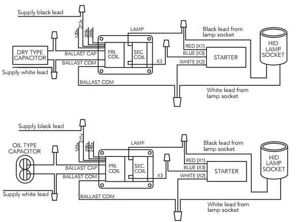
systems are summarized in Table 2. Figure 13
illustrates luminaire wiring diagrams for the various
ballasts used in HID lighting systems. Other
characteristics are as follows:
Ballast Efficiency: No ballast delivers all of the current
passing through it to the lamp it serves. Some power
always is lost in the form of resistance heat. A ballast
that is 90% efficient delivers 90% of the power to the
lamp. The remaining 10% is wasted in heating the ballast.
The ballast watt losses add to the total power consumed.
Line Voltage: For some ballasts, the line voltage as
the lamp starts is less than the final operating voltage.
In these cases, fuses and circuit breaker ratings should
be based on the operating voltage value. For other
ballasts, the starting voltage is considerably higher than
the final operating voltage, so circuit protection must
be sized to accommodate starting voltage levels.
Line Voltage Regulation: Variations in line voltage can
be caused by system demands and other factors.
Newer power systems normally operate within +5% of
the rated system voltage, but in some older systems
the daily voltage variation can be as high as 10%. The
ballast selected must be able to accommodate these
voltage fluctuations.


