
high pressure sodium ballast wiring:
1. Field wiring connections should only be made by qualified personnel.
2. Turn off supply voltage at breaker before accessing fixture Wiring Compartment.
3. Refer to wiring diagram on ballast label for proper component connections (typical connections illustrated above).
4. For safe operation:
a) Ground all system components (metallic case capacitor, ballast core, fixture housing, etc)
b) Insure all unused leads are individually insulated from ground
c) Wire product in accordance with local and national electric codes
d) Never perform maintenance while fixture is energized
5. Reassemble fixture Wiring Compartment after completing wiring connections.
6. Turn on supply voltage at breaker.
Note: Fixtures are typically wired to 277v tap unless otherwise specified. To re-configure for an alternate input voltage tap:
1. Remove BLACK lead from existing ballast input leadwire (typically factory wired to 277v tap)
2. Insulate the unused ballast lead with electrical tape or wire nut.
3. Identify the desired ballast input leadwire (120v lead in illustration above).
4. Strip the desired magnetic ballast leadwire and re-connect BLACK lead with supplied wirenut.
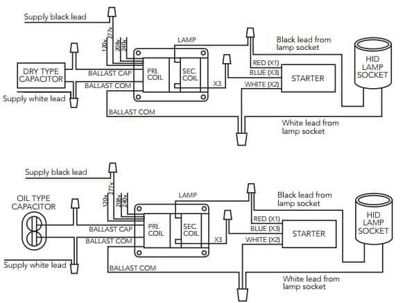
high pressure sodium ballast wiring
Ballast Wiring Diagrams for HID ballast kits including Metal Halide and high pressure sodium ballast wiring. Most magnetic HID ballasts are multi-tap, meaning they can be connected to several different voltages.
Here we display wiring diagrams for metal halide (probe start), metal halide (pulse start) and high pressure sodium HID ballast kits. Most magnetic HID ballasts are multi-tap, meaning they can be connected to several different voltages. Here we display wiring diagrams for metal halide (probe start), metal halide (pulse start) and high pressure sodium ballast.