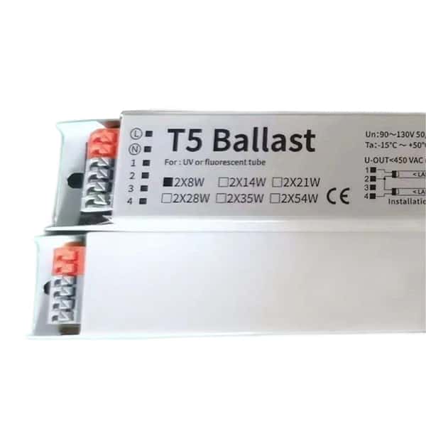
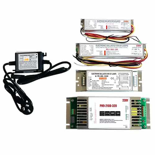
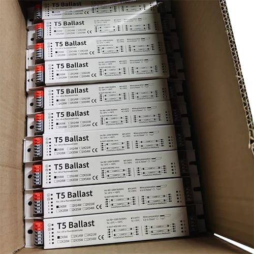
When T5 electronic ballasts encounter issues, it often leads to unexpected lighting failures that can be both costly and inconvenient. Testing a T5 ballast with a multimeter is a straightforward way to troubleshoot problems, verify if the ballast is functioning correctly, and potentially save on replacement costs. Here, we’ll guide you through a step-by-step approach to testing a T5 electronic ballast with a multimeter.
To test a T5 electronic ballast, use a multimeter to check voltage output, resistance, and continuity, ensuring all values are within their specified ranges.
Testing the lamp ballast before assuming bulb failure can help identify the root cause and possibly avoid unnecessary replacement. With this guide, we’ll break down the testing process to ensure your lighting system operates at its best.
Safety First: Precautions Before Testing
Before working with any electrical equipment, especially high-voltage lighting components, prioritize safety. Start by disconnecting the ballast from any power source to prevent electrical shock. When working with electronic ballasts, always wear protective gloves, goggles, and use non-conductive tools. Additionally, discharge the capacitor within the ballast. Capacitors can hold a charge even after the power is disconnected, so carefully use a resistor or insulated screwdriver to release any residual charge. Following these precautions will keep you safe as you work on the ballast.
Setting Up the Multimeter for Ballast Testing
A multimeter is an essential tool for testing the functionality of a T5 ballast. Begin by selecting the right settings on your multimeter. For this test, you’ll use the resistance, voltage, and continuity settings. Ensure your multimeter has reliable test leads, as worn leads can give false readings. Digital multimeters are often more accurate and easier to read than analog ones, though either type can work if properly calibrated. Once your multimeter is ready, you’ll have the right setup to check each function of the ballast with precision.
Testing Continuity in the T5 Ballast
Checking continuity verifies that the ballast’s circuit is unbroken, which is essential for proper function. To test continuity, set your multimeter to continuity mode (usually marked by a diode symbol or sound wave). Place the probes on the two terminals of the ballast’s wiring connections. A continuous circuit should display a reading or emit a sound, confirming an unbroken path. If there’s no response, the circuit may be open or damaged. Continuity testing can often reveal issues such as loose connections or internal wiring problems, both of which disrupt normal ballast function and reduce efficiency.
Checking Voltage Output of the T5 Ballast
Testing voltage output is a crucial step to ensure the ballast is delivering power correctly. To do this, switch your multimeter to the voltage setting, and place the probes on the output terminals of the ballast. Ensure the ballast is properly grounded and connected to a power source for this test. A functional T5 ballast typically has a specific voltage output range, which can vary based on the model. If the voltage reading is within the recommended range, the ballast is likely in working order. Low or no voltage, however, could indicate power supply issues, circuit problems, or internal ballast failure, signaling the need for further investigation or replacement.
Resistance Testing for Ballast Integrity
Resistance testing allows you to assess the integrity of the ballast’s internal coil. Set your multimeter to measure resistance (indicated by the Ω symbol), and place the probes on the ballast coil’s terminals. Functional T5 ballasts have standard resistance values, and a significant deviation from this range suggests potential internal damage. High resistance readings often indicate coil deterioration or circuit wear, which can lead to inefficient power transfer and reduced lighting quality. Low resistance readings, on the other hand, can mean shorted coils or other component failures within the ballast, compromising its reliability.
Troubleshooting Common Ballast Issues Detected with Multimeter
Once you’ve gathered continuity, voltage, and resistance readings, you may notice some common issues that can arise with T5 ballasts. Intermittent voltage output often points to loose connections or faulty internal components. If continuity is absent, it could mean breaks in the internal wiring or damaged connections within the ballast. High resistance readings, which are less common but significant, may indicate a deteriorated coil that’s reducing ballast efficiency. In each case, taking corrective steps, like tightening connections, replacing damaged components, or fully replacing the ballast, can restore function.
When to Replace the Ballast: Signs of Irreparable Damage
After testing, some signs might point to irreparable damage, suggesting that a replacement is the best option. Indicators like consistent low or absent voltage, high resistance, or an inability to establish continuity are often signs that the ballast is beyond repair. Additionally, if the ballast has visible signs of wear, such as corrosion, overheating, or burned areas, it may be best to replace it altogether. Upgrading to a new ballast can enhance lighting performance and often offers increased energy efficiency, extending the lifespan of the overall system.
Final Thoughts
Testing a T5 light ballast with a multimeter is a simple yet effective way to diagnose issues and ensure smooth, reliable lighting operation. By carefully following these steps, you can identify potential problems early and maintain an efficient lighting system.


